On this page you can learn more about:
- Global Positioning System (GPS)
- Space Based Augmentation Systems
- Ground Based Augmentation Systems
- Signal Processing
- GNSS Receiver
- Differential GNSS
- Realtime Kinematics (RTK)
- Single-Antenna GNSS Pseudo-Attitude
- Dual-Antenna GNSS Compass
- Multi-Antenna GNSS Orientation Determination
- Satellite Signal Authentication
- Multi-GNSS
- NavWar
- Anti-Jam Satellite Navigation
Global Positioning System (GPS)
The GPS space segment currently consists out of 31 operational satellites orbiting around the Earth. The U.S. DoD is committed to maintaining the availability of at least 24 operational GPS satellites, 95% of the time, cf. www.gps.gov . GPS satellites are located in Medium Earth Orbit (MEO) at an altitude of approximately 20200 km. Each satellite circles the Earth about twice a day. The satellites are arranged around the Earth on six equidistant orbital planes with an inclination of 55°. Each plane contains four satellites in the specified 24 satellite minimum constellation. There are different generations of GPS satellites in the space.

The signal power available for transmission has in case of block II GPS satellites been published as 27W. This is the power input into the corresponding satellite antenna. The Effective Radiated Power (ERP) depends, due to the satellite antenna gain pattern, on the nadir angle. The major signal loss in the link budget is the free space path loss. The atmospheric loss is almost negligible. The gain of a passive reception antenna varies depending on the elevation angle between typically 0dB at zenithal and less than -30dB in downside direction. The noise, received at the antenna interface is composed out of different parts. The major noise source is the antenna itself due to its physical antenna temperature. Additional noise sources are noise from physical sky radiation or cosmic background radiation and even man made noise. The received signal in zenithal direction can be assumed to be -156dBW, whereas the received noise power at the antenna interface is typically -200dBW/Hz. Depending on the bandwidth of the receiver frontend, the noise power gets up to -126dBW in case of an 20 MHz receiver bandwidth. This values shows that the signal power is far below the natural noise power. In order to use this very low power signal for navigation, the PRN Code (which can be either civil C/A-Code or military P(Y)-Code) is a spread spectrum signal. Within the GPS receiver the phase of this PRN Code is recovered by correlation. Only through this operation, it is possible to raise the navigation signal above noise power. The C/A-Code is generated in baseband within the satellite and afterwards converted up to L1 band by using a sine signal with the frequency of L1 band.
Within the atmosphere, besides of damping, also the signal travel time is influenced by the ionosphere and troposphere. These induced errors on range measurement have to be corrected in order to get a correct position solution. Error models like the “Klobuchar Model” for the ionosphere are used to compensate for these errors. Coefficients of the Klobuchar model are sent as part of the navigation message, which is modulated on the L1 and L2 carrier frequency. The navigation message contains further vital information needed for the GPS receiver to calculate its position. Amongst others these are time stamp of signal transmission, the satellite clock error and ephemeris data out of which the receiver calculates the satellite position.
Positioning solution quality is split into “Dilution of Precision (DOP)” values and the User Range Error (URE). The former describe the influence of the satellite geometry and the latter an assumed homogeneous ranging performance. The PDOP stands for the 3-D position error. TDOP indicates the clock bias estimation error and GDOP combines the PDOP and TDOP. In case the NED frame is used there also exist the horizontal HDOP and the vertical VDOP. In order to get an optimal position solution, the GPS receiver selects out of the satellites in view those satellites which form an optimal configuration. The selection of satellites used within the position solution depends also on the Signal-to-Noise ratio of the particular satellite.
Literature
- Seminar “Navigation and Data Fusion”.
- P. Misra and P. Enge, Global positioning system: Signals, measurements, and performance, 2nd ed. Lincoln, Mass: Ganga-Jamuna Pr, 2011.
- B. W. Parkinson, J. J. Spilker, P. Axelrad, and P. Enge, Global positioning system: Theory and application. Washington, D.C.: American Institute of Aeronautics and Astronautics, 1996.
- E. D. Kaplan, Understanding GPS: Principles and applications. Boston [etc.]: Artech House, 1996.
- G. Xu, GPS: Theory, Algorithms and Applications. Dordrecht: Springer, 2007.
- M. S. Grewal, L. R. Weill, and A. P. Andrews, Global positioning systems, inertial navigation, and integration, 2nd ed. Hoboken, N.J.: Wiley-Interscience, 2007.
- J. A. Farrell and M. J. Barth, The global positioning system and inertial navigation. New York, NY: McGraw-Hill, 1999.
Space Based Augmentation Systems
A GNSS ground control segment cannot give warnings to safety critical users in a timely manner if this service was not foreseen in its system design to be transmitted via the space segment. Standalone GPS receivers thus cannot meet the aeronautical requirements in terms of integrity, continuity and availability. Therefore, a system augmentation became necessary to close the safety gap.
It needs a large number of differential GNSS reference stations to cover a large area. Via geostationary (GEO) satellites, Space Based Augmentation System (SBAS) works in a centralized scheme which provides GEO ranging, integrity and categorized differential corrections to users. SBAS is mainly used by the civil aviation sector. Meanwhile, it is also used in precise agriculture, offshore oil exploration, fleet management, to name just a few. SBAS systems provide decimeter to meter level positioning accuracy. SBAS systems mainly consist of GEO communication satellites, reference station network, terrestrial communication network, master stations, etc.
Reference stations collect GNSS data and forward them to the master station. The master station analyzes, calculates and categorizes the pseudorange errors into satellite ephemeris, satellite clock and ionospheric errors. Furthermore the master station performs integrity monitoring for the user segment.
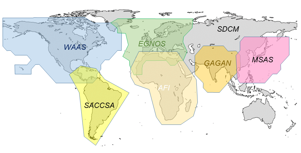
Free SBAS Services
- Wide Area Augmentation System (WAAS), operated by US Federal Aviation Administration (FAA)
- European Geostationary Navigation Overlay Service (EGNOS), operated by European Satellite Services Provider (ESSP) on behalf of GSA.
- System for Differential Correction and Monitoring (SDCM), developed by Russia
- Multi-functional Satellite Augmentation System (MSAS), developed by Japan
- GPS Aided Geo Augmented Navigation system (GAGAN), developed by India
- Satellite Navigation Augmented System (SNAS), proposed by China
Commercial SBAS Services
- StarFire, operated by NavCom Technology, Inc.
- OmniSTAR, Differential GNSS Services of Trimble Navigation Limited
- Starfix, operated by Fugro
- TerraStar from TerraStar GNSS Limited
Current typical standards for civil aviation SBAS equipment are made by RTCA SC 159, including MOPS DO-229, MOPS-DO-228 for Airborne Equipment and Airborne Antenna Equipment, respectively.
Literature
- P. Misra and P. Enge, Global positioning system: Signals, measurements, and performance, 2nd ed. Lincoln, Mass: Ganga-Jamuna Pr, 2011.
- Feder Aviation Administration, Satellite Navigation – WAAS: Hot it works. Available: http://www.faa.gov/about/office_org/headquarters_offices/ato/service_units/techops/navservices/gnss/waas/howitworks/.
- European Space Agengy – navipedia, SBAS Systems. Available: http://www.navipedia.net/index.php/SBAS_Systems.
Ground Based Augmentation Systems
SBAS systems are not reliable enough to support CAT I to CAT III precision approaches. Instead of providing one vector differential correction as SBAS, GBAS forms scalar corrections for each satellite. It is more accurate than SBAS, since a GBAS works as local differential system (usually 23nm radius around airport) and pseudorange error characteristics are more similar, the closer the receivers are located.
GBAS systems are usually composed of:
- Ground Facility: several GNSS antennas, a processing system, a VHF Data Broadcast (VDB) transmitter
- Compatible avionics
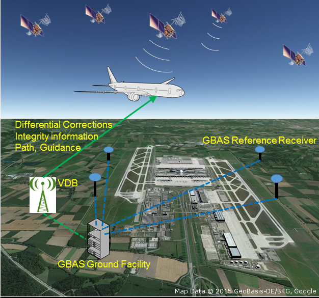
The average ranging error to each satellite is calculated from the several antennas measurements. The ground facility will monitor and analysis the reliability and integrity for each satellite and only send corrections of reliable candidates. Incorporating GBAS aiding, a position estimate can be determined with a very high statistical significance (error probability in the order of 10-7). The VDB messages contain differential corrections and integrity information and are sent through the VHF data link.
GBAS systems can guide the aircraft in an ILS style. Current GBAS system are operational for Cat I approaches. In Germany, it is already used in Bremen and Frankfurt. With continued research and test, GBAS systems will be capable and get operational approval for Cat II/III conditions.
The GBAS Ground Facility also monitors general GPS satellite performance. The GBAS compatible avionics uses only GPS satellites for which it receives valid ground corrections. When the GBAS Ground Facility determines there is a potential problem with a GPS satellite or when it cannot monitor a GPS satellite, it stops broadcasting corrections for that particular satellite, effectively preventing the GBAS avionics from using the satellite.
Literature
- Enge, “Local area augmentation of GPS for the precision approach of aircraft,” Proceedings of the IEEE, vol. 87, no. 1, pp. 111–132, 1999.
- Federal Aviation Administration, Satellite Navigation – GBAS – How It Works. Available:http://www.faa.gov/about/office_org/headquarters_offices/ato/service_units/techops/navservices/gnss/laas/howitworks/.
Signal Processing
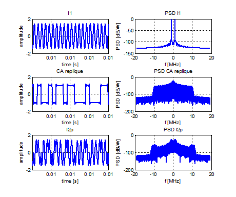
From the signal processing point of view, a GPS receiver can be considered as a Code Division Multiple Access (CDMA) receiver. Satellites transmit their information within the same RF band simultaneously. The signal from different sources can be separated within the receiver because the different pseudorandom signals are orthogonal and public. Each GPS satellite generates two such pseudorandom spread spectrum signals. The civil and known C/A-Code and the military P(Y) code. The C/A-Code has a code length of 1 millisecond and a chip length of one microsecond where its major power is concentrated within a bandwidth of 1.023 MHz. The P(Y) code has a code length of one week and a chip length of 0.1 microseconds and a tenfold spectral extent compared to C/A. The pseudorandom codes are upconverted within the satellites to L1 respectively L2 band and then transmitted towards the Earth.
At the receiver, the signal is damped or amplified by the antenna gain pattern, depending on the elevation. In case of an active antenna, a low noise amplifier is located within the antenna and amplifies the signal about 10 to 40 dB. An amplification near to the antenna should be preferred in order to minimize the overall noise figure of the analogue receiver chain. It follows a distributed amplification and downconversion. Within this stage, the signal is stepwise downconverted to lower intermediate frequencies. Each downconversion is followed by a bandpass filter in order to cancel unwanted conversion products. Also an amplification takes place after each downconversion. Such an approach circumvents the problem of feedback due to a single large amplification. (In case of distributed downconversion, each amplification acts on another frequency whereby a feedback is not possible).
After the last downconversion step, which is usually realized by undersampling instead of using multiplier based conversion, an Automatic Gain Control follows. This unit measures the maximum amplitude of the signal (which is the noise, because satellite signal is below the noise) and amplifies the signal about such an amount that the complete range of values within the following quantization unit is exploited. A typical value for the final intermediate frequency is 10 MHz with a typical sampling frequency between 30 and 40 MHz. The signal at this intermediate frequency is split in two signal paths. The signal paths are multiplied with about 90 degree phase shifted carrier repliquas. The results are the I and Q signals at baseband. In case of a perfect synchronized carrier replique regarding frequency and phase, the satellite signal is exclusively in the I path. In the Q path then there is no signal but noise. In case of an imperfect synchronized carrier replique, the power of the satellite signal is shared between the I and Q paths.
The I as well as the Q path are split into three signal subpaths respectively. The three I and Q channels are now multiplied with the C/A-Code or P(Y)-Code replique. One channel is respectively multiplied with an early version of the C/A-Code, which means, this replique is shifted half a chip-length in time forward. The second channel of the I and Q paths are multiplied with the prompt version of the replicated C/A-Code. The third I and Q paths are multiplied with a late version of the C/A-Code replique. This multiplication in time space describes a convolution in frequency space. The spectrum of the received C/A-Code is convoluted with the spectrum of the replicated C/A-Code. If the received signal is interfered with a jammer, this jammer signal will also be convoluted with the spectrum of the replicated C/A-Code. In case of a narrowband jamming signal (bandwidth of jammer is lower than 1.023 MHz in case of a C/A-Code replique) the spectrum of the jammer is “spreaded”, which means that the spectrum of the jammer is extended, whereas the average Power Spectral Density (PSD) of the jammer spectrum gets lower.
After this spreading operation, in each signal path an “Integrate and Dump” operation is applied. The signal is summed up for at least 1ms (depending on the correlation time). This operation is mathematically equivalent with convoluting the signal with a rectangular impulse of the same duration. This convolution in time space describes a multiplication with the Fourier transform of the rectangular impulse in frequency space. The Fourier transform of a rectangular impulse is a sinc function with its first zero at the inverse of correlation time. Thus the postcorrelation noise power consists only out of the small amount of power constraint within the bandwidth of the inverse of correlation time.
Literature:
- L. Peterson, R. E. Ziemer, and D. E. Borth, Introduction to spread-spectrum communications. Englewood Cliffs NJ: Prentice Hall, 1995.
- G. Proakis, Digital communications, 4th ed. Boston: McGraw-Hill, 2007.
- D. Kammeyer, Nachrichtenübertragung: Mit 468 Abb. u. 35 Tab, 5th ed. Wiesbaden: Vieweg + Teubner, 2011.
- A. Richards, Fundamentals of radar signal processing, 2nd ed. New York, NY: McGraw-Hill Education, 2014.
GNSS Receiver
A GNSS receiver can be split in different stages. The first stage is called the “Analog Low Noise Amplificiation and IF Signal Generation Unit”. It contains the antenna, the low noise distributed amplification and downconversion stages, the automatic gain control and the sampling unit. This stage outputs the sampled raw signal at IF frequency which is fed into the next stage which is called “correlation unit”.
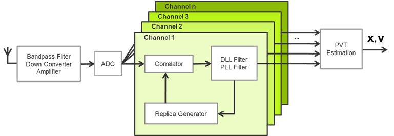
Within the correlation unit, at first the “carrier wipe off” takes place, which means that the IF signal is converted with the help of a carrier replique to baseband and split into an I and Q signal. In case of a perfectly synchronized carrier replique, only the I channel contains the satellite signal, whereas the Q channel only contains noise and distortions. The baseband I and Q signals are correlated with Early-, Prompt- and Late Code replique signals. The results are six correlator outputs which are used by codephase and carrierphase discriminators to measure the phase error between carrier or code replique signals and the received ones. The correlation unit is executed with the IF sampling frequency. The frequency of the correlator outputs depends on the correlation time.
The next stage is called the tracking stage. Inputs to the tracking stage are the discriminator outputs. The task of the tracking stage is to generate the steering commands for carrier replique and code replique generation. There are a lot of different architectures to realize the tracking. The classic approach tracks each channel separately, where the steering commandos are generated by PID controllers. Instead of PID controllers, optimal control strategies, incorporating Kalmanfilters, can be used.
A sophisticated approach is the combined tracking of all satellite channels by using a Kalmanfilter based vector tracking filter. In case of scalar tracking, the tracking unit outputs pseudoranges and pseudorange rates. In case of vector tracking, the outputs can be also pseudoranges and pseudorange rates, but can even be position and velocity, mostly in ECEF coordinates. Some more supporting functions are necessary within a GNSS receiver. This includes for example the acquisition unit. The acquisition unit determines the code phase offset for the replicated CA-Code with an accuracy of at least an half CA-Code chip. The determined offset is used by the tracking unit as initialization.
Literature
- Seminar “Navigation and Data Fusion”.
Differential GNSS
Classical GNSS technique can improve the positioning errors to meter level. The further potential lies in the fact that GNSS signals have high spatial and temporal error characteristics for not too far (tens to hundreds kilometers) dislocated receivers. GNSS satellites work at an orbit height of about 20.000 km. Signal propagation paths from the satellite to receivers are tightly related, when the receivers are operated in distances of not more than hundreds of kilometers near Earth, i.e. strong correlations of ionospheric and tropospheric errors can be expected in many situations.
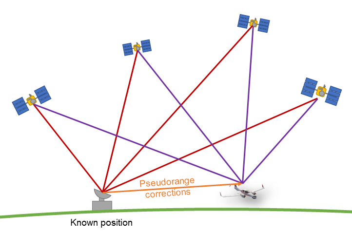
The pseudorange error (more commonly called differential correction) for each satellite can be determined by a reference station at a known location for all satellites above the horizon and then be transmitted to users via radio link if real-time operation is required. Spatial and temporal decorrelation should be considered and applied. For marine or land applications, a widely used standard format for data communication is RTCM 10403.2 Version 3.0 from the Radio Technical Commission for Maritime Services (RTCM). RTCM defines the physical interface and logical data messages between reference stations and user receivers. Since aviation industry placed more stringent requirements on integrity and reliability, other augmentation schemes and systems became necessary, cf. abstracts on Integrity, SBAS, GBAS for more details.
Literature
- Differential GNSS (Global Navigation Satellite Systems) Services, RTCM 10403.2, 2013.
- Misra and P. Enge, Global positioning system: Signals, measurements, and performance, 2nd ed. Lincoln, Mass: Ganga-Jamuna Pr, 2011.
- W. Parkinson, J. J. Spilker, P. Axelrad, and P. Enge, Global positioning system: Theory and application. Washington, D.C.: American Institute of Aeronautics and Astronautics, 1996.
Realtime Kinematics (RTK)
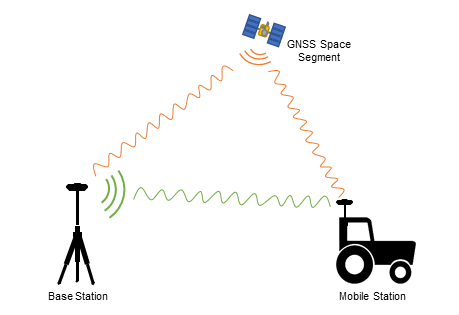
Accuracy of the GNSS positioning for a standalone user is in general predefined with some meters, originating from different code phase error sources in the GNSS. A possible reduction of those higher effects can be obtained using reference stations and DGNSS concepts that permit a positioning with sub-meter accuracy. Higher GNSS positioning precision in the sub-decimeter level can be achieved by carrier phase measurements and ambiguity resolution of the carrier wave length. This technique is commonly known as Real Time Kinematic and based on the signal processing of the user receiver and reference station measurements at the same time. Thus the user equipment requires a data link between reference station and remote receiver and an option for time synchronization of both systems measurements.
The RTK Algorithms are based on single and double differencing of the range and most relevant phase measurements in order to eliminate the dominating error effects. In the single difference equation the influences of atmosphere are greatly reduced, but not yet the clock errors of different receivers. Using the double differencing method the remaining clock errors can also be eliminated and the carrier phase based ranging process obtains – in the absence of cycle slips – the accuracy of some fraction of a carrier wave length, when resolving double difference ambiguities corresponding to user and reference station observations.
The initial ambiguity resolution represents the kernel challenge for this method of precise positioning that requires the minimization of a residual function. The solution of this problem is treated separately, e.g. utilizing the LAMBDA method, to resolve the true integer ambiguity sufficiently fast.
Summarizing the Real Time Kinematic algorithms are much more complex than the conventional GNSS receiver positioning and are originally coming from surveying with geodetic receivers applying post processing. The centimeter positioning accuracy permits a wide range of applications, requiring a sufficiently dense network of reference stations for service coverage in large areas.
Literature
- Petevello, GNSS Solutions: Network RTK: What is the effect of user and CORS height on NRTK performance? Available: http://www.insidegnss.com/auto/SEPOCT13-SOLUTIONS.pdf.
- WANG, “Stochastic Modeling for Real-Time Kinematic GPS/GLONASS Positioning,” Navigation, vol. 46, no. 4, pp. 297–305, 1999.
- Cordesses, C. Cariou, and M. Berducat, Precision Agriculture, vol. 2, no. 2, pp. 147–161, 2000.
- Eisfeller, “Real Time Kinematic and Precise Point Positioning: Status and Trends,” Schriftenreihe Geoinformationsdienst der Bundeswehr, vol. 87, no. 2012, pp. 47–57.
Single-Antenna GNSS Pseudo-Attitude
A GNSS receiver in general derives position information from pseudoranges to a sufficient number of satellites and velocity information from Doppler frequency measurements of the platform, where it is mounted on.
For straight and level flight conditions of fixed wing aircraft and when wind velocity is negligible compared to airspeed, GNSS velocity vector azimuth gives a good estimate of aircraft heading. Similarly, aircraft pitch angle can be computed as the sum of climb angle and angle of attack estimate in wings level flight. Very simple relationships of angle of attack and flight state may yield sufficiently accurate results. Use of more detailed models of the carrier aerodynamics can increase accuracy, but at the same time makes the solution aircraft specific. Furthermore the wind speed should either be known by air data measurements or be negligible with respect to the aircraft’s velocity. For estimation of aircraft pitch using climb angle and angle of attack in general flight conditions, roll angle must be known.
To achieve an additional roll angle estimate different strategies are possible. On the one hand the often highly accurate Doppler velocity can be time-derivated in order to receive the aircraft acceleration with respect to Earth. The acceleration direction vector within maneuvers can be used as roll angle indicator for a bank-to-turn fixed-wing aircraft (specific force parallel to b z-axis). Accelerations around zero thus would relate to roll angles around zero. On the other hand the procedure of attitude determination can be completed with a roll angle estimation based on the antenna model and prediction of the satellite constellation. In general the GNSS antenna has an almost hemispherical reception pattern and various damping ratio for receiving signal at different elevation angles. This system specific of the common GNSS antenna provides a possibility for dynamically estimation of the roll angle, using the state observation of visible satellites and corresponding carrier to noise values. This procedure requires the knowledge of the GNSS antenna reception pattern. A combination of both methods appears to offer further improvement of single-antenna roll angle estimation. Incorporating a roll rate gyro measurement would provide better performance. This approach could serve as primary navigation means in some smoothly-operated low-cost non-critical applications or as part of the degradation concept of simplex navigation system architectures.
Literature
- P. Kornfeld, R. J. Hansman, and J. J. Deyst, “Single-Antenna GPS-Based Aircraft Attitude Determination,” Navigation, vol. 45, no. 1, pp. 51–60, 1998.
- P. A. Lievens, J. A. Mulder, and P. Chu, “Single GPS Antenna Attitude Determination of a Fixed Wing Aircraft Aided with Aircraft Aerodynamics,” in Guidance, Navigation, and Control and Co-located Conferences, AIAA Guidance, Navigation, and Control Conference and Exhibit: American Institute of Aeronautics and Astronautics, 2005.
- Wang and R. A. Walker, “Single Antenna Attitude Determination for Fedsat with Improved Antenna Gain Patterns,” in The 6th Inertnational Symposium on Satellite Navigation Technology Including Mobile Positioning & Location Services, Melbourne, Australia, 2003.
- Axelrad and C. P. Behre, “Satellite attitude determination based on GPS signal-to-noise ratio,” Proc. IEEE, vol. 87, no. 1, pp. 133–144, 1999.
Dual-Antenna GNSS Compass
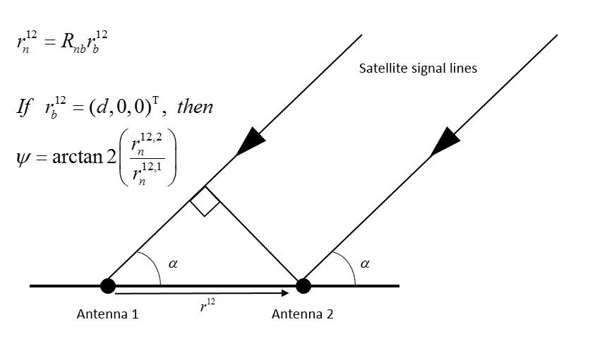
Heading of a vehicle can be determined by the means of satellite navigation. The approach requires that two antennas are attached to the vehicle and that a carrier phase difference along with satellite and antenna position information are available. This allows to compute n-frame baseline vector whose coordinates in body frame are predefined by installation. Under certain antenna installation assumptions heading becomes an explicit function of n-frame baseline vector coordinates. The most challenging part of direction computation algorithm is determination of initial ambiguities.
Ambiguity search technique, ambiguity function method, time-difference and space-difference approaches belong to traditional methodologies of ambiguity determination. Baseline rotation method, which belongs to space-difference methodology, proposes to apply several rotations about two axes and to measure carrier phase before and after every rotation. Collected data is then used to obtain ambiguity-free measurements and to solve for baseline direction. Typical performance of GNSS compass depends strongly on baseline length and vary from 0.5 deg for 0.5 meter to 0.1 deg for 10 meters baseline.
Literature
- M. Peng, F. R. Chang, and L. S. Wang, “Rotation Method for Direction Finding via GPS Carrier Phases,” IEEE Transactions on Aerospace and Electronic Systems, vol. 36, no. 1, 2000.
- Chansik Park, Ilsun Kim, Gyu-In Jee, and Jang Gyu Lee, “An error analysis of GPS compass,” in SICE ’97. 36th SICE Annual Conference. International Session Papers, pp. 1037–1042.
- D. Groves, Principles of GNSS, inertial, and multisensor integrated navigation systems, 2nd ed. Boston, Mass.: Artech House, 2013.
Multi-Antenna GNSS Orientation Determination
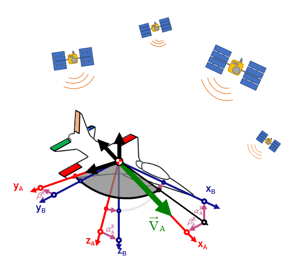
Although it was not the original intention, GNSS technology provides means to estimate vehicle’s orientation with respect to local frame. Orientation can be uniquely determined provided that at least three non-collinear antennas are installed onboard. Antennas positions define body-fixed vectors, which are called baselines. Body-frame coordinates of baseline vectors are considered known since they can be determined either by calibration or during a precise mechanical installation.
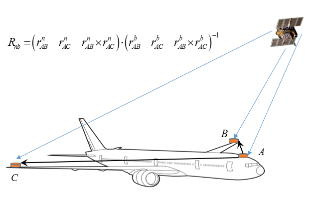
Knowledge of both NED- and body-frame coordinates of two non-collinear vectors allow to solve for the corresponding rotation matrix. However reasonable accuracy can only be achieved if a carrier-phase measurement is available, which requires that integer ambiguities are resolved. Least-squares AMBiguity Decorrelation Adjustment (LAMBDA) is the most commonly used method for integer estimation. Accuracy of GNSS-based orientation solution depends strongly on baseline length. Longer distances between antennas reduce significantly measurement errors and improve total performance. Four or greater number of antennas can be used to increase system’s reliability and to provide redundancy. Typical GNSS-determined orientation accuracy is of about 1 degree.
Literature
- J. Teunissen, “The Least-squares Ambiguity Decorrelation Adjustment: a Method for Fast GPS Integer Ambiguity Estimation,” Journal of Geodesy, vol. 70, pp. 65–82.
- A. Farrell and M. J. Barth, The global positioning system and inertial navigation. New York, NY: McGraw-Hill, 1999.
- D. Groves, Principles of GNSS, inertial, and multisensor integrated navigation systems, 2nd ed. Boston, Mass.: Artech House, 2013.
Satellite Signal Authentication
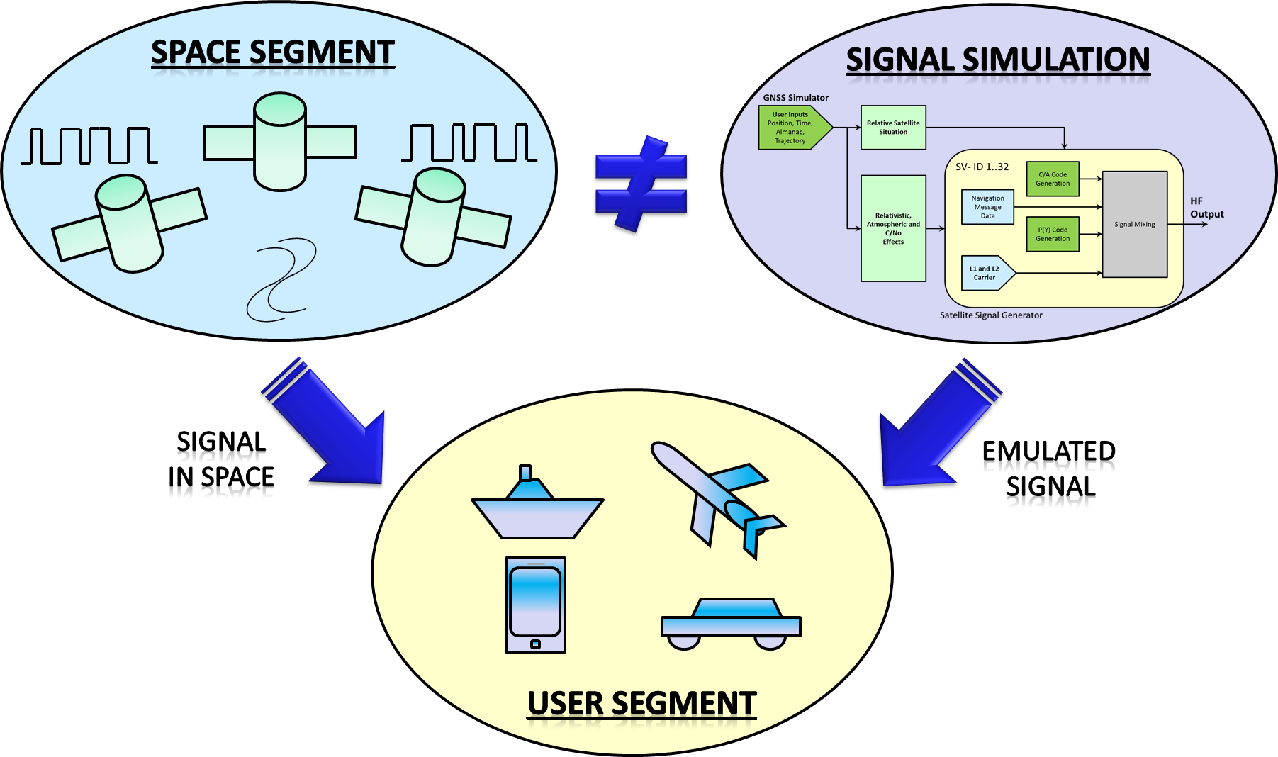
The public service GNSS signals in space are publicly known and used for the positioning in civil applications. Moreover the GNSS space segment simulators use the knowledge of the civil signal composition for their radio frequency output generation related to the desired GNSS constellation and receiver trajectory. When the synthetic signals from space segment simulators are transmitted into space, it could compromise the proper signal processing of receivers in their surroundings.
With some tracking of an airborne platform a conscious attack on its navigation system by manipulated or even false GNSS signals is not just feasible, but already present, since spoofing and meaconing equipment is available off-the-shelf. The resulting vulnerability of the civil usage of satellite navigation is the basis for the requirement of GNSS signal authentication. Military signals are due to their inherent encryption just exposed to so-called meaconing, i.e. the sequential reception and transmission of GNSS signals.
Single antenna satellite navigation receivers have some limited potential for the authentication of signals in space. A satellite signal authentication approach can in general use any combination of the underlying signal characteristics:
- Signal carrier
- Civil (unencrypted) code
- Navigation message monitoring
- Military (encrypted) code
- Signal strength (unfortunately just lower limit specified)
- Time of arrival
- Reception signal polarization
- Cross frequency signal correlation
- Cross receiver signal correlation
- Satellite provided signal authentication (not available)
- Consistency with external sensors
- Space segment simulator signal specific effects
Literature
- Lo, and D. De Lorenzo et al, Signal Authetication: A Secure Civil GNSS for Today. Available: http://www.insidegnss.com/auto/sepoct09-Lo.pdf.
- Wesson, M. Rothlisberger, and T. Humphreys, Practical Cryptographic Civil GPS Signal Authentication. Available: https://radionavlab.ae.utexas.edu/images/stories/files/papers/nma.pdf.
- G. Kuhn, Signal Authentication in Trusted Satellite Navigation Receivers. Available: http://www.cl.cam.ac.uk/~mgk25/gps-auth.pdf.
- Heng, D. Chou, and G. X. Gao, Cooperative GPS Signal Authenticaation from Unreliable Peers. Available: http://gracegao.ae.illinois.edu/publications/conference/2014_ION%20GNSS_E6b_Cooperative%20Authentication_Gao.pdf.
- G. T. Becker, and S. C. Lo et al, Secure Location Verification: A Security Analysis of GPS Signal Authentication. Available: http://waas.stanford.edu/papers/Becker_DBsec_2010_CameraReady.pdf.
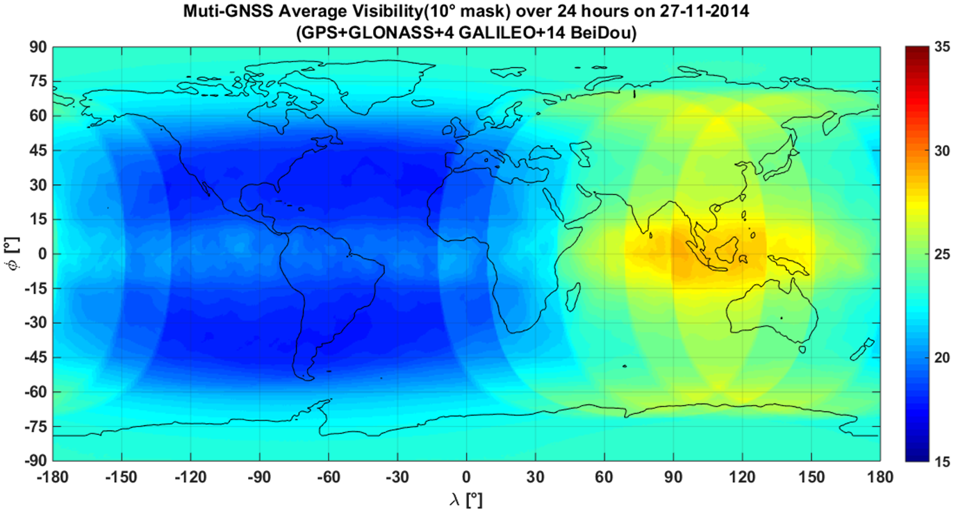
Multi-GNSS
According to actual proposals there will be more than 120 navigation satellites in the sky after the year 2020. Global Navigation Satellite Systems (GNSS) in general transmits a variety of codes modulated on multiple frequency carriers, which increases robustness. GNSS navigation performance is sensitive to the available number of satellites and their geometry. The biggest advantage of Multi-GNSS for users thus is the increased number of visible satellites along with an improved geometry. This is of utmost importance for the direct reception of satellite navigation signals in urban canyons or between mountains inspite the underlying geometry. With more available satellites in view accuracy, integrity, availability and continuity can in general be improved.
GNSS show differences in carrier signal frequency, code signal design, geodetic datum, navigation messages including ephemeris, ionospheric delay and satellite clock errors. Users can benefit from multiple frequencies regarding ionospheric delay, multipath and man-made interference. More civil frequencies can be used to fasten carrier phase ambiguity resolution for precise positioning applications. Advanced Receiver Autonomous Integrity Monitoring (ARAIM) supports LPV-200.
Maintenance of satellite navigation systems requires fielding of new generations of satellite blocks with in general increased performance into mixed satellite constellations. Thus the problem arises to find the GNSS positioning solution involving the best combination of satellite ranging accuracy and geometry. Hence satellite selection and weighting will be one of the key issues in Multi-GNSS positioning.
GPS alone cannot meet the requirements of availability and continuity of practical RNPs due to insufficient number of satellites, whereas Multi-GNSS makes it feasible. U.S. Federal Aviation Administration (FAA) Next Generation Air Transportation System (NextGen) primarily relies on GNSS to generate its Automatic Dependent Surveillance-Broadcast (ADS-B) for Air Traffic Control (ATC) containing aircraft’s identification, (2D GNSS) location, (barometric) altitude and speed. Europe at the same time concentrates its future Air Traffic Management (ATM) efforts in the program Single European Sky ATM Research (SESAR). The goal is to improve flight and airspace efficiency and safety.
Literature
- J. Blanch, T. Walter, and P. Enge, “Satellite navigation for aviation in 2025,” Proceedings of the IEEE – Special Centennial Issue, vol. 100, pp. 1821–1830, 2012.
- A. Simsky, “Three’s the charm: triple-frequency combinations in future GNSS,” Inside GNSS, no. 5, pp. 38–41, 2006.
- G. X. Gao and P. Enge, “How Many GNSS Satellites are Too Many?,” IEEE Transactions on Aerospace and Electronic Systems, vol. 48, no. 4, pp. 2865–2874, 2012.
NavWar
Global navigation satellite systems are a powerful means of global positioning. Operating in Medium Earth Orbit (MEO) at L-Band is a well-accepted compromise for both, global visibility over the horizon and signal propagation disturbance through atmosphere. Due to the power limitations caused by solar panels in day-night operation, the effective transmission energy of a satellite is limited to the power consumption of a light bulb. Mainly due to free-space path loss, i.e. the conic signal propagation from the satellite towards the Earth and its vicinity, the received power levels can get as low as 10-16 Watts for GPS. Thus the received signal power is several magnitudes below background noise. Spread spectrum techniques allow to establish signal-to-noise ratios of about 50 dB.
Satellite navigation signals are known with respect to common carrier frequency, individual code and navigation message. For military usage the navigation satellites provide separate encrypted signals. Meaconing is an electronic warfare technique to receive satellite signals and directly transmit it in order to challenge users with content wise valid satellite signals, which can in general be detected through signal authentication or integrity monitoring. Spoofing requires to be able to generate a content wise valid satellite signal, which is therefore limited to civil users by definition. But even for civil users it is difficult to create a signal which will not be detected by signal authentication or integrity monitoring. Jamming relies on increasing the background noise in the one or other way in order to hide the signal such far below the noise, that signal tracking gets broken inside the user GNSS receiver. More or less spoofing and jamming is a matter of effort on both sides, the interfering source and the protecting user equipment. Interferences due to technical malfunctions have been repeatedly reported and cannot be avoided. Certification rule makers thus will be forced to require anti-jam satellite navigation in most applications.
Literature
- R. Clynch, and A. A. Parker et al, The Hunt for RFI – Unjamming a Coast Harbor. Available: http://gpsworld.com/the-hunt-rfi/.
- PMA 209 USER’S CONFERENCE, GPS AIR NAVIGATION OVERVIEW, Program Executive Office, Command, Control, Communications, Computers and Intelligence (PEO C4I), Communications Program Office (PMW/A 170), March 2010
Anti-Jam Satellite Navigation
The received satellite signal at the GNSS receiver antenna is very weak. Its power is approximately -156dBW. This signal is even below the natural noise, for which a power spectral density of -200 dBW/Hz can be assumed.
Depending on the bandwidth of the analog chain, typical 2 MHz, the noise power output by the sampling unit is -137 dBW. Within the following correlation unit, the signal power is raised above noise power by correlation.
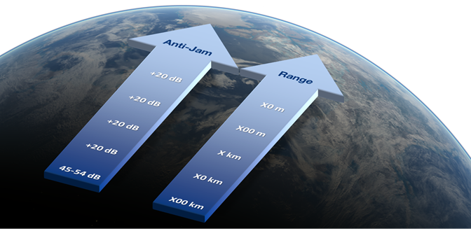
A problem arises if the GNSS signal is being jammed. There are different jamming signal types, but one of the worst one is a white noise jammer where the jamming power is concentrated within a bandwidth a 0.5 MHz or less. Assuming for example a 1kW jammer and distance between jammer and receiver of 100km, the receiver’s antenna is still hit by a jamming power spectral density of ~-150dBW/Hz which exceeds the natural noise floor tremendously.
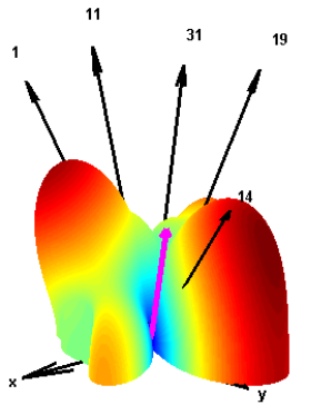
In such a scenario, tracking wouldn’t be possible anymore if not some antijam measures within the GNSS receiver are realized. In each receiver stage, different antijam measures are possible. Starting with the antenna: instead of passive single patch antenna’s, antenna arrays could be used for simple nulling the antenna gain pattern in direction to the jammer.
More antijam is gained by using an array antenna for beamforming to maximize the antenna gain pattern in direction to the satellite and minimize the gain pattern in direction to the jammer. Also the whole amplification chain within the analog receiver stage has to be optimized to get a small overall noise figure and in turn a better antijam. Within the correlation unit, a longer correlation time, using P-Code instead of CA-Code and choosing the right discriminator function are the main measures to improve antijam.
Even the tracking architecture itself has tremendous influence on the GNSS receiver’s robustness against jammer. Also the aiding quality and aiding frequency determines the bandwidth of the tracking channel. A good aiding quality allow’s the tracking loop to reduce it’s bandwidth which in turn improves the antijam. Moreover, using vectortracking instead of classical scalar tracking also leads to a higher antijam.
| ⇦ Inertial Navigation | return to overview | Navigation Aids ⇨ |