On this page you can learn more about:
- Inertial Sensors
- Stationary Alignment
- Inertial Navigation
- Aerobatic & All-Earth Navigation
- Inertial Sensor Error Propagation
- Schuler-tuned Gyrocompass
- Dead Reckoning
- Attitude/Heading Reference Systems
Inertial Sensors

Inertial sensors allow the measurement of 6DoF-motion without the need of any signal reception. The two most common inertial sensor types are accelerometers and gyroscopes, often shortened as gyro. As implied by their name, accelerometers measure linear acceleration and gyros angular rates or their timely integrals in case of integrating inertial sensors. In many applications, multiple accelerometers and gyroscopes are combined into an Inertial Measurement Unit (IMU).
The most common accelerometer technologies can be grouped into these three categories:
- Pendulum accelerometers measure the inertial force on a proof mass in the form of its deflection from the zero-load position (open loop) or in the form of necessary power to keep the proof mass in its initial position (closed loop).
- Vibrating bar accelerometers (VBA) measure the inertial force on a proof mass as a load-induced change of oscillation frequency of a vibrating structure that constrains the proof mass.
- Pendulum Integrating Gyro Accelerometers (PIGA) are mechanical gyroscopes with a mass asymmetry that converts linear acceleration into a torque.
The classical pendulum accelerometer as well as the VBA are also available as cheap Micro Electro Mechanical Systems (MEMS) for a wide range of applications.
Gyroscope technologies can be grouped in the following three categories:
- Mechanical gyroscopes are based on the gyroscopic forces that act on a spinning wheel. If the gyroscope is rotated around an axis (input axis) that is perpendicular to the wheel’s rotation axis, the gyroscopic forces will tend to align the wheel’s rotation axis to this input axis. Analogous to the accelerometers, these forces respectively moments can be measured open loop or closed loop.
- Optical gyroscopes are based on the Sagnac effect. Light is sent in both directions of a closed optical path. Rotation of this path leads to a phase-difference of the two beams. This effect is used in the Fiber Optic Gyroscopes (FOG) as well as the Ring Laser Gyroscopes (RLG).
- Coriolis Vibratory Gyroscopes (CVG) measure the Coriolis forces that act on a resonator, due to its rotation. This principle is used in MEMS tuning-fork gyroscopes as well as vibrating shell gyroscopes.
Every sensor technology has its very own characteristics and error sources. Therefore specific testing and calibration procedures are required for each type of sensor.
Literature
- Seminar “Navigation and Data Fusion”.
- A. Lawrence, Modern inertial technology: Navigation, guidance, and control, 2nd ed. New York, NY: Springer, 2001.
- D. H. Titterton and J. L. Weston, Strapdown inertial navigation technology, 2nd ed. Stevenage: Institution of Electrical Engineers, 2009.
- Š. Merhāv, Aerospace sensor systems and applications. New York: Springer, 1996.
- NATO Research and Technology Organisation, “Advances in Navigation Sensors and Integration Technology: EN-SET-064”.
Stationary Alignment
For starting inertial navigation the initialization of position, velocity and orientation is required.
Position may have been stored, can be entered manually or derived from satellite positioning. Velocity may initially be zero with respect to Earth or also taken from satellite navigation Doppler. Thus most crucial for inertial navigation is its initialization with attitudes, i.e. roll and pitch angles, and north-indicating heading.
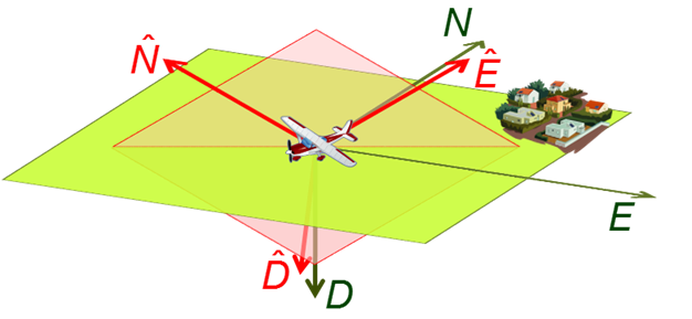
When initially at rest with respect to the Earth the accelerometer triad indicates the gravity vector, the gyro triad the Earth’s rotation vector and a 3D magnetometer the magnetic field gradient. Gravity herein is the by far strongest signal. From any directional observation two rotational degrees of freedom can be derived. The rotational component around the observed direction always is not observable by definition. The proceeding to derive the attitudes from the gravity observation is called levelling, since it is equivalent to calculating the horizon. The process of deriving the north-indicating heading from gyro measurements is called gyro-compassing for which quite accurate gyros are required due to the low Earth rotation rate of just about 15°/h. When less accurate gyros are available often a 3D magnetometer is used instead for this purpose. In some applications the heading is stored and thus just levelling needed to complete orientation. But this approach requires that the platform is not moved when the navigation system is not powered.
Transfer alignment is used when a (slave) navigation system starts to operate and another (master) navigation system is already available. This is for example the case when outer loads attached to aircraft stores get powered. Finally in-motion alignment is performed when the spatial direction of the specific force sensed by the accelerometer triad is redirected by manoeuvers in order to change the currently not observable orientation component. Finally inertial mechanizations are available which are very tolerant to initial heading errors.
Literature
- Seminar “Navigation and Data Fusion”.
- B. Scherzinger, “Inertial Navigator Error Models for Large Heading Uncertainty,” in Position Location and Navigation Symposium, Atlanta, GA.
Inertial Navigation
According to Newtonian physics the measurements of the inertial sensors Leveling and gyrocompassing using inertial sensorsare made with respect to inertial space.

In order to integrate inertial sensor measurements for spatial velocity and position, gravitation and inertial accelerations have to be corrected. As the Earth is in free fall in the gravitational field of extra-terrestrial masses the centre of mass of the Earth is acceleration-free. Due to the deviation of the user from the geocentre the so-called tidal acceleration remains, which is just to be considered for very precise inertial navigation applications.
Inertial accelerations are centrifugal, Euler and Coriolis accelerations. Since Earth’s rotation is uniform in very good approximation, the Euler acceleration can be neglected. The Earth’s gravity field, as superposition of gravitation and centrifugal acceleration, has to be considered at least in form of a flattened ellipsoid of revolution, corresponding to Somigliana’s normal gravity formula. Precise inertial sensors or applications in mountainous areas can require more accurate gravity field modelling, e.g. derived from EGM2008.
In a sequential process of levelling and gyro compassing the initial orientation could be derived, when the Earth’s rate of rotation can be sufficiently resolved by the gyro triad. Inertial navigation using integrating inertial sensors can be realized by either applying single or dual frequency algorithms.
Literature
- Seminar “Navigation and Data Fusion”.
- C. Jekeli, Inertial navigation systems with geodetic applications. Berlin: de Gruyter, 2001.
- J. Dambeck and B. Braun, “A Single Frequency Strapdown Algorithm for Integrating IMUs in ECEF-Frame,” in Advances in Aerospace Guidance, Navigation and Control, 2011.
Aerobatic & All-Earth Inertial Navigation
Inertial navigation algorithms are initially formulated using rotation matrices.
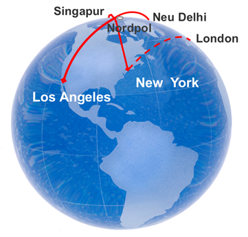
Preserving orthonormality has then to be explicitly considered due to numerical effects. Commonly 3-dimensional parametrizations of the group of rotation matrices are introduced to avoid the orthonormality constraints. It can be proven that all 3-dimensional parametrizations of rotation matrices show some kind of deficiencies. For example the Euler angles show singularities in vertical flights. Through the introduction of 4-dimensional quaternions with a normalization constraint this limitation can be overcome. Thus a regular integration even in looping flights is granted.
A similar singularity is associated with the geographic poles. Mainly the transport rate gets singular, which has the task to keep the computational frame levelled and North-indicating. The definitions of longitude and North-indicating heading cause the singularity.
Splitting the North-indicating heading into wander angle and wander azimuth and rearranging the inertial navigation equations allows to introduce a position quaternion with a corresponding regular angular rate. Hence the resulting all-Earth inertial navigation differential equations remain regular at the geographic poles and thus just the algebraic transformations into commonly used navigation states is affected in the direct vicinity of the geographic poles.
Literature
- Seminar “Navigation and Data Fusion”.
- J. Stuelpnagel, “On the Parametrization of the Three-Dimensional Rotation Group,” SIAM Review, vol. 6, no. 4, pp. 422–430, 1964.
- W. A. Poor, “A Geometric Description of Wander Azimuth Frames,” Journal of the Institute of Navigation, vol. 36, no. 3, 1989.
Inertial Sensor Error Propagation
Navigation states initialization errors, inertial sensor triads measurement errors and especially gravity model errors are propagated through application of nonlinear inertial navigation ordinary differential equations.
The nonlinear navigation error ordinary differential equations can be derived by decomposition of the true quantities in their corresponding approximations and errors and are to be used in a sigma point (unscented) Kalman filter.

The linearized navigation error ordinary differential equations are the basis for navigation state covariance propagation and correction in an extended Kalman filter. Traditionally the condition number of the resulting dynamic matrix was improved by introducing navigation states of similar size. Therefore necessary transformations have been nonlinear, elaborative and complicated.
Commonly simplifications have been introduced to reduce the computational effort. Due to the sake of modern digital computing the corresponding needs have been reduced. Today therefore different mechanizations will be used. Nevertheless the error state space remains the preferred space for navigation data fusion due to the inherent reduction from platform dynamics to the much lower error dynamics.
For sufficiently precise inertial sensors the inertial navigation ordinary differential equations just show second order nonlinearities due to the central gravity field on the one hand and curvilinear translational and rotational navigation states on the other hand. Since data fusion relies for the distribution of innovations solely upon the estimated co-variances, a proper navigation error propagation is essential.
Literature
- Seminar “Navigation and Data Fusion”.
- A. Dachs, “Rechenzeitoptimierung, Robustifizierung und Tuning eines Kalmanfilters zur Datenfusion für Navigationsanwendungen,” Schriftenreihe Geoinformationsdienst der Bundeswehr, no. 3, 2010.
Schuler-tuned Gyrocompass
A gyrocompass uses the Earth’s rotation to indicate the direction of true north. In contrast to a magnetic compass, the gyrocompass does not rely on the local magnetic field and is thus not influenced by disturbances of the magnetic flux.
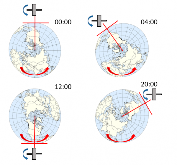
Classical mechanical gyrocompasses are based on a spinning rotor that is mounted on a gimbaled platform. For the simplest approach, additional weights are attached to the gimbal in order to align it with the local vertical. Gravity creates a torque whenever the rotation axis is not perpendicular to horizontal plane. Due to conservation of angular momentum this results in a rotation perpendicular to both spin and torque and causes the precession of the spin axis. The axis describes a cone whose horizontal plane section is an ellipse centered about north-south line. Finally, the spinning axis will indicate the true north direction.
If the platform is accelerated, the pendulum mass used to align the platform to the local vertical will tilt and thus cause a false heading information. In 1923 Maximilian Schuler showed that this effect does not occur if the pendulum reaches the Earth’s center. The period of such a theoretical pendulum is about 84 minutes. Though such a pendulum exists in theory only, accelerometer-servo-loops used to align the platform are tuned to a period of 84 minutes in order to reduce acceleration sensitivity. This is called “Schuler-Tuning”.
Still, a gyrocompass is subject to certain errors which are related to the vehicle’s motion. Typical accuracy of estimated heading is 0.1 degrees, which is comparable to navigation-grade INS.
Literature
- D. Groves, Principles of GNSS, Inertial and Multisensor Integrated Navigation systems, 2nd edition, Artech House, 2013
- Lawrence, Modern inertial technology: Navigation, guidance, and control, 2nd ed. New York, NY: Springer, 2001.
- G. Major, Quo vadis: Evolution of modern navigation: The rise of quantum techniques. New York u.a.: Springer, 2014.
Dead Reckoning
Dead reckoning is a method of computing vehicle’s current position given a knowledge of previously determined position and estimated velocity. Since measurements are conventionally made in vehicle’s body frame, a heading or full orientation information may be required to integrate motion with respect to Earth. Due to velocity magnitude and direction errors with respect to Earth the resulting position error will grow over time. In straight and levelled motion with constant heading error the position error growth will be linear over time and thus may be advantageous in the long run compared to navigation methods with a nonlinear position error growth.
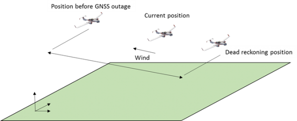
Traditional marine navigation is a classic example of dead reckoning. Speed of a ship with respect to water can be measured by a marine speed log. Formerly an actual wooden log was used for that purpose to measure the speed of drift between a ship and its surrounding water. Prior knowledge of sea currents would of course improve accuracy. After the speed is measured, position increments can easily be calculated given magnetic heading and time elapsed since previous position determination.
Nowadays there exist a wide variety of dead reckoning techniques for different navigation applications on land, at sea or in air. Among them are aerodynamic model aided navigation, visual odometry, Air Data Systems (ADS), Doppler velocity log, Dual Airborne Laser Scanner (DALS), conventional odometry or pedestrian pedometer.
Literature
- P. D. Groves, Principles of GNSS, inertial, and multisensor integrated navigation systems, 2nd ed. Boston, Mass.: Artech House, 2013.
Attitude/Heading Reference Systems
Attitude and heading (orientation) information is crucial for safely controlling any aircraft.
If a visual flight is not possible, a technical aid is needed to provide an estimate about the most important flight states. The same applies in case attitude and heading are controlled automatically. The instrument that computes this estimate is called Attitude and Heading Reference System (AHRS). Requirements on integrity and availability of the AHRS are high because of its importance for safe operation of an aircraft. That is why use of robust aircraft-autonomous measurements is paramount.

Classical AHRS solutions use gyroscopes to measure vehicle’s angular rate and to integrate orientation differential equation. In order to meet operational requirements and to avoid systematic loss of accuracy, Earth’s rotation rate and vehicle’s transport angular rate shall be accounted for and compensated. Classical AHRS architectures that are suitable for most of the application usually require rate sensors accuracy of 0.1 to 1 degree per hour.
Earth’s gravity and magnetic fields, which can be measured directly in straight-and-level flight situations, provide information on platform’s attitude and magnetic heading and can be used to either aid inertial AHRS or to provide a direct reference of vehicle’s orientation. However direct reference of attitude from sensed acceleration is lost when the platform is accelerated. Earth’s magnetic field on the other hand can be corrupted by disturbances from ground and under-ground sources so that local field may differ in direction and magnitude. Classical designs thus incorporate air data to compensate Earth’s rotation and transport rate, which are latitude, height, northern and eastern velocity dependent. An so-called Air Data AHRS (AD-AHRS) thus provides attitudes, heading, height, height rate and airspeed to feed the most important cockpit instruments.
Literature
- J. A. Farrell, Aided navigation: GPS with high rate sensors. New York, NY: McGraw-Hill, 2008.
- P. D. Groves, Principles of GNSS, inertial, and multisensor integrated navigation systems, 2nd ed. Boston, Mass.: Artech House, 2013.
| ⇦ Geodesy | return to overview | Satellite Navigation ⇨ |